

By: Dalton Bell, Staff Platform Engineer at Aston Technologies, Inc.
Introduction
At Aston Technologies, we are committed to providing lab environments for our engineering staff to test new implementations, learn new skills, and share knowledge with fellow engineers. GNS3 has seen significant adoption in the network engineering space as an environment to host networking labs. While working in a standalone GNS3 environment is generally a good experience, we wanted to provide a means for multiple engineers to collaborate on topologies and to build topologies with resource requirements that could exceed the capacity of one of our compute nodes. To accomplish this, we decided to create a distributed GNS3 environment.
Outline
1. Solution Overview
2. Understanding the Overlay
3. Implementing the Automation
4. Day0 to DayN operations
5. Utilizing the Fabric
Solution Overview
Requirements:
- The fabric should support multi-tenancy by exposing multiple L2 and L3 VPNs
- Engineers should be able to interface with the fabric using standard networking concepts like BGP and 802.1q once working within a topology.
- Changes to the fabric should be orchestrated via some automation toolchain.
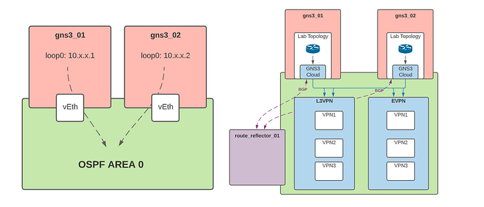
Architecture: Our architecture consists of two or more GNS3 worker nodes which host topologies, a route reflector to distribute BGP across our GNS3 nodes, and a border leaf, which provides external connectivity at both L2 and L3 for services external to the fabric. Our border leaf maintains an eBGP relationship with a PfSense VM, which handles all Internet-bound NAT, and injects a default route into the INET VPN, which simulates internet connectivity.
Control Plane: Since the GNS3 server VM is built on top of Ubuntu, we decided to implement all the underlying networking in Linux using the FRR package. FRR is a full-featured routing stack that allows us to run protocols like BGP, OSPF, and MPLS/LDP.
Underlay: We use OSPF to build an underlay network and advertise loopback interfaces that serve as next-hops for iBGP
Overlay: We rely heavily on BGP to provide our overlay by using MPLS L3VPNs to provide L3 services and BGP EVPN to provide L2. GNS3 servers advertise L3VPN and EVPN routes to the route-reflector, distributing the information to the rest of the nodes. Within the GNS3 server topologies, virtualized network devices connect to Linux bridges via the Cloud appliance. These bridges serve as the entry points to the various VPNs. GNS3 servers then tunnel traffic between themselves for inter-host connectivity.
Automation: We chose to automate the configuration of the VMs and networking in Ansible, a strong leader in the space of programmatically managing Linux servers. We run all our configuration management with two ansible roles. These roles contain tasks to bootstrap the GNS3 servers with the required packages and make changes to the kernel to support features like MPLS. They also implement the underlying Linux networking configurations and tie them to a systemd service to persist on reboots, modify the server filesystem to persist project data across rebuilds, and install the FRR configuration that brings up our fabric control plane.
We run our instance orchestration through Terraform, and Terraform gives us the ability to manage our instance lifecycle declaratively. Our terraform codebase references a base template used during instance creation and calls Ansible to complete the first provisioning step via a local provisioner.
Understanding the Overlay
Let's take an automation detour for a bit to cover some networking concepts and explain how all of these processes move traffic between our servers.
MPLS L3VPN
To build MPLS VPNs, we need a few components.
VRF — Each MPLS VPN ties to a VRF created in Linux.
Bridge Interface — This is the interface assigned to the VRF that in-project devices will use to peer over BGP and forward VPN destined traffic.
LDP — LDP Distributes MPLS labels between routers participating in MPLS.
MP-BGP — Used as the control plane to distribute prefixes along with route-distinguishers to identify which VRF the prefix belongs to.
Once LDP is up between the servers, they will share MPLS labels for each route in the RIB.
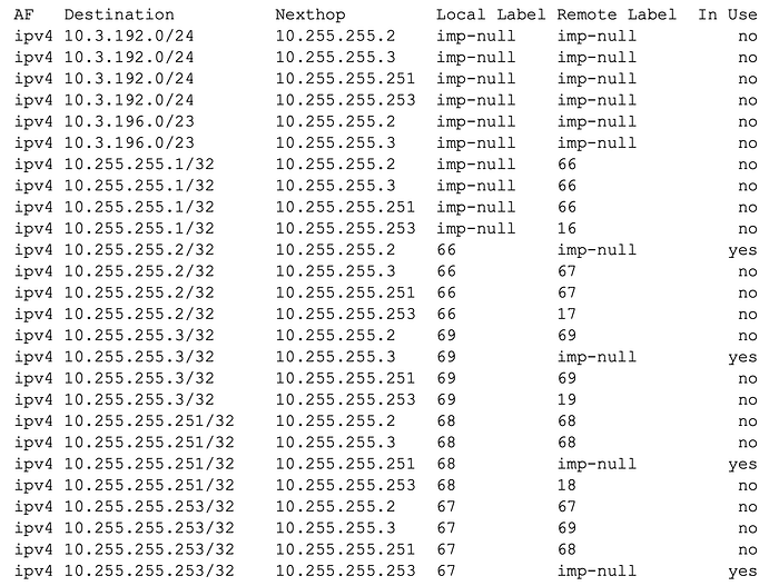
We can see in this output that all servers have learned about the MPLS label for the loopbacks advertised into OSPF; we can refer to this as the transport label. The transport label will use this label to forward traffic to the advertising server.
Each VRF is configured with a route-distinguisher associated with a VPN.
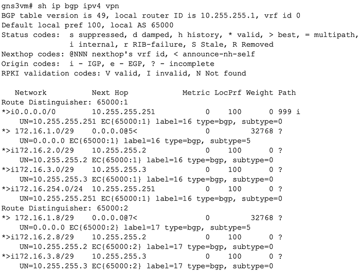
Here, we can see that an additional label is associated with each prefix learned via L3VPN; we can refer to this as the VPN label. Based on this output, 172.16.1.0/29 is local to this server (next hop 0.0.0.0). When a host in 172.16.1.0/29 sends traffic to a host in 172.16.2.0/29, a few things are going to happen:
First, the sending host will look up the transport label associated with the next hop for that prefix.
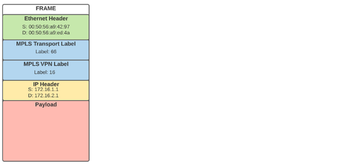
ipv4 10.255.255.2/32 10.255.255.2 66 imp-null yesThe sending host will add that label to the stack and then add the VPN label to the stack.
*>i172.16.2.0/29    10.255.255.2             0    100      0 ?
UN=10.255.255.2 EC{65000:1} label=16 type=bgp, subtype=0
The frame will look like this:
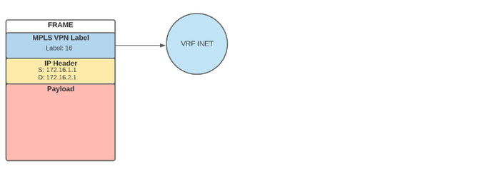
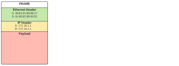
Once received by the remote server, the transport label will be stripped away, and the VPN label will be used to place the traffic into the proper VRF.
Now that the packet is in the correct VRF, it can be forwarded as native IP.
BGP EVPN
We use BGP EVPN to provide L2 VPN services across GNS3 servers in the fabric. This allows engineers to build topologies across multiple servers while maintaining L2 adjacencies or to simulate cases where a service like VPLS is in place.
There are a few components to the EVPN Solution:
Bridge interfaces — These provide the local MAC address learning
VxLAN interfaces — These facilitate the remote mac-address learning and forwarding
MP-BGP — BGP provides the control plane by which the GNS3 servers advertise learned mac addresses and their respective VNIs.
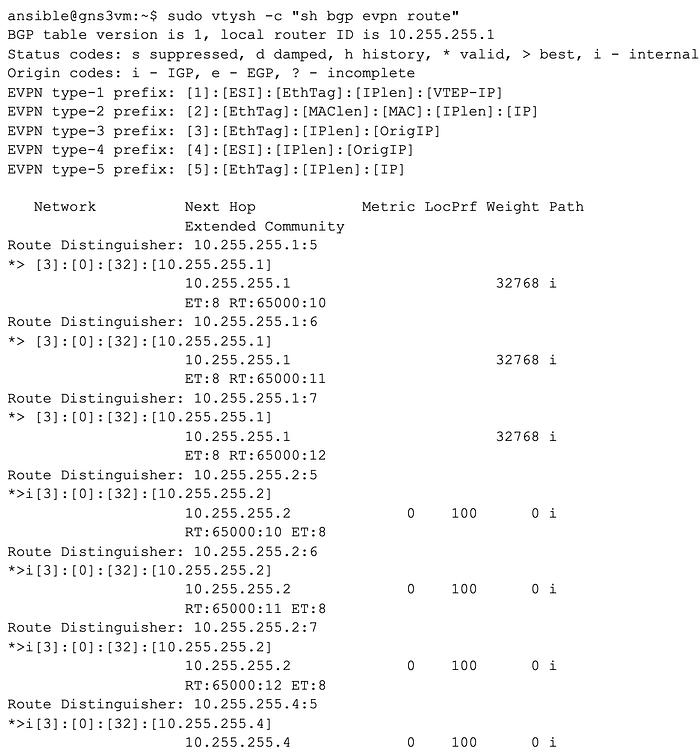
Once peered with the route-reflector, servers will begin advertising their VNIs and MAC addresses and learning about other server advertisements.
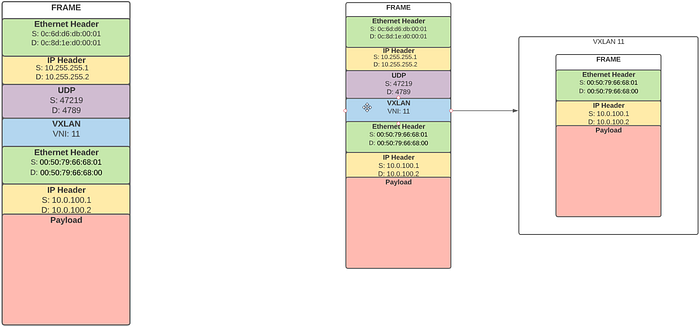
When traffic is initiated from an in-topology device towards a device on another server in the same broadcast domain, the UDP and VXLAN header will encapsulate the packet.
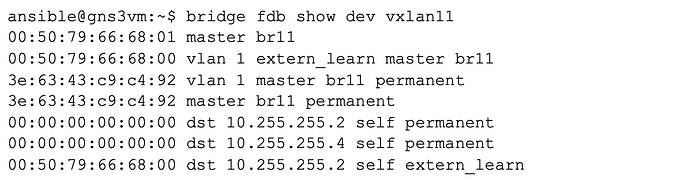
FRR will program the bridge FDB with the MAC address information for hosts behind other VTEPs, as learned from EVPN.
The traffic will be encapsulated with a UDP header and a VXLAN header. The outer IP header will use the loopback interface of the gns3 server advertising the remote mac address as a next hop.
Once the packet is routed to the remote server, the outer headers can be stripped away, and the frame can then be placed in the proper VXLAN domain based on the VNI and forwarded from the VTEP towards the interface of the in-topology device.
Implementing The Automation
At Aston Technologies, we build all our servers from base golden images that are right-sized for our requirements and pre-baked with SSH keys and Ansible user accounts for our ansible control node. We deploy these VMs into our virtualization environment via Terraform. From Terraform, we execute a provisioner playbook that bootstraps our hosts with the required packages, configures a remote filesystem to persist project data across instance rebuilds, and installs a Netplan config for our desired static IPv4 address assigned to the instance. Once our Terraform provisioning is complete, we run a fabric management playbook that ensures all our nodes have the most up-to-date configuration.
Our repository is organized as follows:
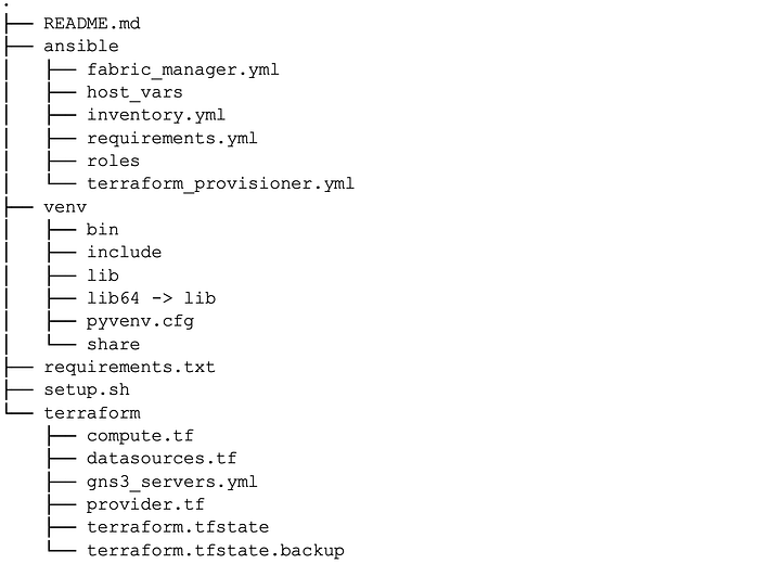
We store our terraform and ansible code in top-level directories and run all orchestration from the root.
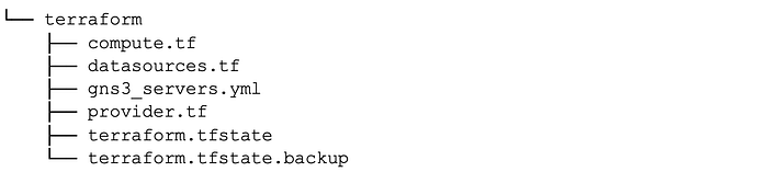
Exploring the Terraform Codebase
Within the terraform codebase, we define various configuration files that contain:
- Our VM template
- Data sources file that pulls in references to our infrastructure needed to provision VMS
- A provider file
- A YAML document that describes our GNS3 server nodes
name: oplab-gns3-01
dataplane_ip: 10.3.192.8/24
name: oplab-gns3-01
dataplane_ip: 10.3.192.9/24
name: oplab-gns3-03
dataplane_ip: 10.3.192.10/24
name: oplab-gns3-04
dataplane_ip: 10.3.192.11/24
We define all the servers managed by Terraform in a YAML document and load it in with the YAML decoder; this makes managing the inventory a bit more human-friendly.
Our YAML file defines the instances and the eventual static IP assigned to the instance; this address will get provisioned by Ansible via a Netplan template.
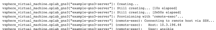
The magic happens in our compute.tf file, which reads in the YAML and provisions VMs based on our base image. Terraform runs two provisioners, a remote-exec which ensures that we can connect to the instance over the dynamic IP grabbed during instance creation, and a local exec which calls an Ansible playbook.
Exploring the Ansible Playbooks
Our ansible directory contains two playbooks, two roles, Hostvars, and an inventory.
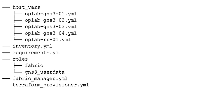
The terraform provisioner playbook calls on two roles, fabric and gns3_userdata, while the fabric manager playbook calls only on the fabric role.
---
- hosts: all
  roles:
    - roles: fabric
      become: yes
    - role: gns3_userdata
      become: yes
---
- hosts: all
  roles:
    - role: fabric
      become:
Exploring the gns3_userdata role
The GNS3 user data role contains tasks to create a directory on an NFS share to store project data and modify the GNS3 server filesystem to use a symlink to the NFS share instead of the default project directory to store projects. This allows us to retain project data when instances need to be rebuilt.
Most of the tasks in our role are contained in the task file user_data.yml, and we also build some additional tasks to migrate servers we may currently have in production that we stood up before the persistent storage implementation.
In our user_data task file, we ensure that the packages needed to work with NFS are present.
We then create a directory to store the project data and connect it to the NFS share.
We then use the hostname passed in from Terraform to name a new directory on our share.
Finally, we check the state of the project directory; if the directory exists, we will remove it and add the symlink.
All these tasks are tagged with user data to reference them when calling playbooks that include the role.
Exploring the fabric role
The fabric role has a lot more going on under the hood; it contains workflows for installing FRR and modifying the server to support MPLS, building out a shell script to manage the Linux networking and tying it to a systemd service, and generating FRR configurations based on host_var data and templates. We will examine the code one task file at a time.
bootstap.yml
We start by running an apt upgrade. This step helps us to avoid issues that can present themselves when our server base images have not changed for a while. Without this step, it is easy to run into corner cases like a deb package failing to add due to the server not having up-to-date TLS certs.
We then add the FRR apt repository and install FRR and supporting packages. Retries are added to this task to provide some resiliency during the provisioning process. Without it, the playbook may fail to due dpkg lock issues.
We then update the FRR daemons file to include the daemons we need FRR to start.
bgpd=yes
ospfd=yes
ospfd_instances=100
ospf6d=no
ripd=no
ripngd=no
isisd=no
pimd=no
ldpd=yes
nhrpd=no
eigrpd=no
babeld=no
sharpd=no
pbrd=no
bfdd=no
fabricd=no
vrrpd=no
pathd=no
We update the sysctl.conf file to enable MPLS support per interface and IP forwarding.
net.ipv4.ip_forward=1
net.mpls.conf.eth0.input=1
net.mpls.platform_labels=100000
We push in a Netplan config based on a J2 template. This variable gets supplied by Terraform at execution time.
network:
  ethernets:
    eth0:
      addresses:
      - {{ dataplane_ip }}
      mtu: 9000
      gateway4: 10.3.192.1
      nameservers:
        addresses:
        - 10.1.249.105
        - 10.1.249.106
        search: []
  version: 2
Finally, we update modules.conf to enable the MPLS kernel module.
# /etc/modules: kernel modules to load at boot time.
mpls_router
mpls_iptunnel
provision_fabric_service.yml
While FRR can manage Linux networking constructs and overlay routing protocols on top of them, we need to create the required interfaces, VTEPS, and VRFs directly in Linux. We achieve this by building a shell script from a J2 template and Ansible host variables, pushing it to the hosts, and tying it to a systemd service to persist across instance reboots.
[Unit]
Description=Provision fabric service.

[Service]
Type=simple
ExecStart=/bin/bash /root/fabric_provision.sh

[Install]
WantedBy=multi-user.target
The systemd service links to our fabric_provision.sh script and runs the shell script upon instance startup.
The J2 template uses conditionals to check if certain keys are defined in the host_var file. This allows us to reuse the same template across different node types. Route reflectors, for example, do not need the VXLAN, VRF, and bridge components and require a loopback to advertise into OSPF.
The data required to populate the shell script comes from an host_var file named after the node.
Provision_frr.yml
We utilize the same templating workflow to configure the routing protocols required to make the fabric operational; we then push these configs to the /etc/frr directory, where they are loaded in at application startup.
To start, we update our vtysh config and remove the frr.conf file. We do this to use individual .conf files instead of the default behavior of a single config file.
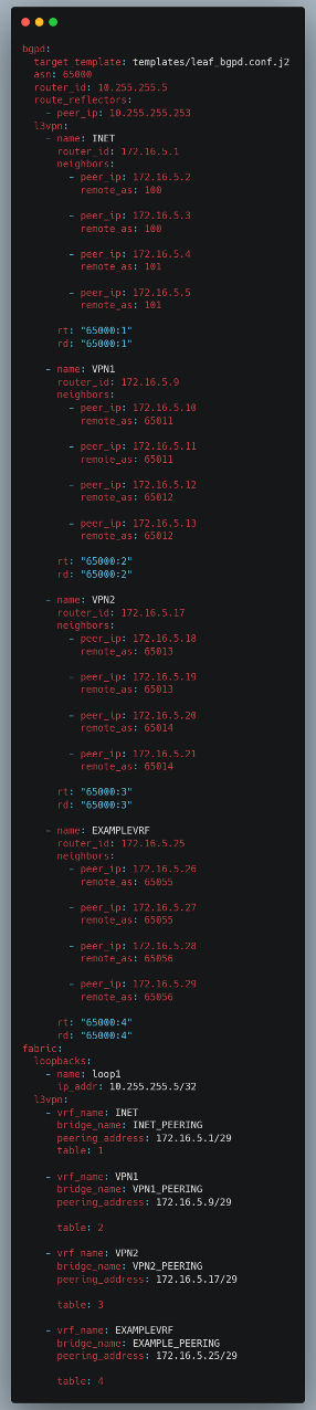
For each routing daemon, we generate a config file based on a J2 template and ansible host_vars. For BGPD specifically, our route reflectors have a different enough config that we needed to build two separate templates. We define a target template as a file reference within the host_vars document to get around using conditionals or additional logic within Ansible. This allows us to look up the required template at run time based on the role of the device.
Our bgpd.conf template for a gns3 server and Hostvars section, which defines bgpd variables
Our ospfd and ldpd configs , while much simpler, utilize the same templating process.
mpls ldp
 router-id {{ldpd.router_id}}
 !
 address-family ipv4
  discovery transport-address {{ldpd.router_id}}
{% for entry in ldpd.interfaces %}
  !
  interface {{entry.interface_name}}
  !
{% endfor %}
 exit-address-family
 !
!
ldpd:
  router_id: 10.255.255.1
  interfaces:
    - interface_name: eth0
Note that each daemon is stored under a corresponding daemon key within the host_var file, this allows us some more flexibility when expressing networking configurations that may share common key-value pair names while avoiding situations where we need to name something "ldpd_router_id" and "ospfd_router_id"
{% for entry in ospfd.interfaces %}
interface {{entry.name}}
 ip ospf {{ospfd.instance_id}} area {{entry.area}}
!
{% endfor %}
!
router ospf {{ospfd.instance_id}}
 ospf router-id {{ospfd.router_id}}
 exit
Handlers.yml
We use Ansible handlers to trigger actions based on the results of tasks defined in the role. Handlers allow us to do things like restart a software process or load in a config based on changes to a particular file. This is especially powerful when considering that the fabric_manager playbook is run against all hosts in a deployment. Still, only a few hosts may receive an updated playbook execution config. Without handlers, we would need to either run restart tasks against all nodes all the time or use some conditional logic within the playbook that checks the status of previous tasks.
Handlers connect to tasks via the notify keyword. This task, for example, notifies the Load BGPD handler based on changes to the bgpd.conf file.
- name: add bgpd config
  ansible.builtin.template:
    src: "{{ bgpd['target_template'] }}"
    dest: /etc/frr/bgpd.config
  become: yes
  become_method: sudo
  tags: frr
  notify:
    - Load BGPD config
    - Save config
Day0 to DayN operations
Day0 Provisioning of a New Server
When provisioning a new GNS3 server for additional lab capacity, the only requirement is a server hostname and static IP.
- name: example-gns3-server
  dataplane_ip: 103.192.20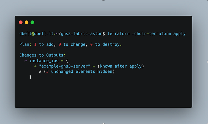
From Terraform apply, the new instance will be provisioned, the provisioning playbooks will run, and we will be left with an instance ready to join the fabric.
If you are interested in seeing the full results of the Terraform apply, please click here.
To join an instance to the fabric, we need to update the Ansible inventory and build out a new host_var file; an easy path for this process is simply copying a config from a server already in production and updating the addressing info for a new host.
This Hostvars file is based on another server currently in production.
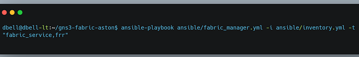
When we call the fabric_manager playbook, we run the fabric_provision and frr tasks against every host in the deployment. This ensures that all nodes are continuously updated with the latest configuration. The Ansible tasks within all the playbooks are intended to be idempotent, and we can see that behavior in the playbook output. Ansible reports many changes to the new example gns3 server and only a few changes for our route reflector.
We can trigger some route diagnostics using the route_diag tag, which issues show commands against each router to view network information like protocol neighbors and learned routes. Running this a few moments after configuration can tell us if our server has successfully joined the network.
We can see that the gns3-server-01 has formed a neighbor relationship with our new server.
We can see that gns3-server-01 has formed a neighbor relationship with our new server
ok: [oplab-gns3-01] => {
"ospf_neighbor.stdout_lines": [
"",
"OSPF Instance: 100",
"",
"",
"Neighbor ID     Pri State           Dead Time Address         Interface                        RXmtL RqstL DBsmL",
"10.255.255.2      1 2-Way/DROther     31.432s 10.3.192.9      eth0:10.3.192.8                      0     0     0",
"10.255.255.3      1 Full/Backup       33.175s 10.3.192.10     eth0:10.3.192.8                      0     0     0",
"10.255.255.4      1 Full/DR           34.361s 10.3.192.11     eth0:10.3.192.8                      0     0     0",
"10.255.255.5      1 2-Way/DROther     34.796s 10.3.192.20     eth0:10.3.192.8                      0     0     0",
"10.255.255.251    1 2-Way/DROther     32.179s 10.3.192.251    eth0:10.3.192.8                      0     0     0",
"10.255.255.253    1 2-Way/DROther     33.161s 10.3.192.253    eth0:10.3.192.8                      0     0     0"
]
}
We can also see that our new server has formed a neighbor relationship with our route reflector.
ok: [example-gns3-server] => {
"bgp_summary.stdout_lines": [
"",
"IPv4 Unicast Summary (VRF default):",
"BGP router identifier 10.255.255.5, local AS number 65000 vrf-id 0",
"BGP table version 0",
"RIB entries 0, using 0 bytes of memory",
"Peers 1, using 723 KiB of memory",
"Peer groups 1, using 64 bytes of memory",
"",
"Neighbor        V         AS   MsgRcvd   MsgSent   TblVer  InQ OutQ  Up/Down State/PfxRcd   PfxSnt Desc",
"10.255.255.253  4      65000        45        15        0    0    0 00:06:40        NoNeg    NoNeg N/A",
"",
"Total number of neighbors 1",
"",
"IPv4 VPN Summary (VRF default):",
"BGP router identifier 10.255.255.5, local AS number 65000 vrf-id 0",
"BGP table version 0",
"RIB entries 5, using 920 bytes of memory",
"Peers 1, using 723 KiB of memory",
"Peer groups 1, using 64 bytes of memory",
"",
"Neighbor        V         AS   MsgRcvd   MsgSent   TblVer  InQ OutQ  Up/Down State/PfxRcd   PfxSnt Desc",
"10.255.255.253  4      65000        45        15        0    0    0 00:06:40           16        3 N/A",
"",
"Total number of neighbors 1"
]
}
Checking the L3VPN routes lets us know that our new server is learning routes from existing servers via the route reflector.
ok: [example-gns3-server] => {
"l3_vpn.stdout_lines": [
"BGP table version is 10, local router ID is 10.255.255.5, vrf id 0",
"Default local pref 100, local AS 65000",
"Status codes:  s suppressed, d damped, h history, * valid, > best, = multipath,",
"               i internal, r RIB-failure, S Stale, R Removed",
"Nexthop codes: @NNN nexthop's vrf id, < announce-nh-self",
"Origin codes:  i - IGP, e - EGP, ? - incomplete",
"RPKI validation codes: V valid, I invalid, N Not found",
"",
"   Network          Next Hop            Metric LocPrf Weight Path",
"Route Distinguisher: 65000:1",
"*>i0.0.0.0/0        10.255.255.251           0    100      0 999 i",
"    UN=10.255.255.251 EC{65000:1} label=16 type=bgp, subtype=0",
"*>i10.0.100.0/24    10.255.255.1             0    100      0 100 ?",
"    UN=10.255.255.1 EC{65000:1} label=16 type=bgp, subtype=0",
"*>i100.64.1.1/32    10.255.255.1             0    100      0 100 ?",
"    UN=10.255.255.1 EC{65000:1} label=16 type=bgp, subtype=0",
"*>i172.16.1.0/29    10.255.255.1             0    100      0 ?",
"    UN=10.255.255.1 EC{65000:1} label=16 type=bgp, subtype=0",
"*>i172.16.2.0/29    10.255.255.2             0    100      0 ?",
"    UN=10.255.255.2 EC{65000:1} label=16 type=bgp, subtype=0",
"*>i172.16.3.0/29    10.255.255.3             0    100      0 ?",
"    UN=10.255.255.3 EC{65000:1} label=16 type=bgp, subtype=0",
"*>i172.16.4.0/29    10.255.255.4             0    100      0 ?",
"    UN=10.255.255.4 EC{65000:1} label=16 type=bgp, subtype=0",
"*> 172.16.5.0/29    0.0.0.0@8<               0         32768 ?",
"    UN=0.0.0.0 EC{65000:1} label=16 type=bgp, subtype=5",
"*>i172.16.254.0/24  10.255.255.251           0    100      0 ?",
"    UN=10.255.255.251 EC{65000:1} label=16 type=bgp, subtype=0",
"Route Distinguisher: 65000:2",
"*>i172.16.1.8/29    10.255.255.1             0    100      0 ?",
"    UN=10.255.255.1 EC{65000:2} label=17 type=bgp, subtype=0",
"*>i172.16.2.8/29    10.255.255.2             0    100      0 ?",
"    UN=10.255.255.2 EC{65000:2} label=17 type=bgp, subtype=0",
"*>i172.16.3.8/29    10.255.255.3             0    100      0 ?",
"    UN=10.255.255.3 EC{65000:2} label=17 type=bgp, subtype=0",
"*>i172.16.4.8/29    10.255.255.4             0    100      0 ?",
"    UN=10.255.255.4 EC{65000:2} label=17 type=bgp, subtype=0",
"*> 172.16.5.8/29    0.0.0.0@10<              0         32768 ?",
"    UN=0.0.0.0 EC{65000:2} label=17 type=bgp, subtype=5",
"Route Distinguisher: 65000:3",
"*>i172.16.1.16/29   10.255.255.1             0    100      0 ?",
"    UN=10.255.255.1 EC{65000:3} label=18 type=bgp, subtype=0",
"*>i172.16.2.16/29   10.255.255.2             0    100      0 ?",
"    UN=10.255.255.2 EC{65000:3} label=18 type=bgp, subtype=0",
"*>i172.16.3.16/29   10.255.255.3             0    100      0 ?",
"    UN=10.255.255.3 EC{65000:3} label=18 type=bgp, subtype=0",
"*>i172.16.4.16/29   10.255.255.4             0    100      0 ?",
"    UN=10.255.255.4 EC{65000:3} label=18 type=bgp, subtype=0",
"*> 172.16.5.16/29   0.0.0.0@12<              0         32768 ?",
"    UN=0.0.0.0 EC{65000:3} label=18 type=bgp, subtype=5",
"",
"Displayed  19 routes and 19 total paths"
]
}
There are additional verification checks that run for EVPN and LDP.
Day N: Provisioning a new L3VPN between two or more servers
Assume we would like to build out a new L3VPN between two servers. We could achieve this by editing our host variables file for all desired nodes and rerunning the fabric_provision and FRR playbooks.
In this example, we have configured a new L3VPN as EXAMPLEVRF on server 04 and implemented a similar configuration on the example server.
Running the playbook should update the fabric provision service, restart it, and update the bgpd configuration for frr.
View the playbook execution Gist
Rerunning our route_diag task list shows us that both servers advertised our new VPN to the route reflector.
TASK [fabric : show l3vpn] ****************************************************************************************************************************************************************************************************************
ok: [oplab-rr-01] => {
"l3_vpn.stdout_lines": [
"BGP table version is 9, local router ID is 10.255.255.253, vrf id 0",
"Default local pref 100, local AS 65000",
"Status codes:  s suppressed, d damped, h history, * valid, > best, = multipath,",
"               i internal, r RIB-failure, S Stale, R Removed",
"Nexthop codes: @NNN nexthop's vrf id, < announce-nh-self",
"Origin codes:  i - IGP, e - EGP, ? - incomplete",
"RPKI validation codes: V valid, I invalid, N Not found",
"",
"   Network          Next Hop            Metric LocPrf Weight Path",
"Route Distinguisher: 65000:1",
"*>i0.0.0.0/0        10.255.255.251           0    100      0 999 i",
"    UN=10.255.255.251 EC{65000:1} label=16 type=bgp, subtype=0",
"*>i10.0.100.0/24    10.255.255.1             0    100      0 100 ?",
"    UN=10.255.255.1 EC{65000:1} label=16 type=bgp, subtype=0",
"*>i100.64.1.1/32    10.255.255.1             0    100      0 100 ?",
"    UN=10.255.255.1 EC{65000:1} label=16 type=bgp, subtype=0",
"*>i172.16.1.0/29    10.255.255.1             0    100      0 ?",
"    UN=10.255.255.1 EC{65000:1} label=16 type=bgp, subtype=0",
"*>i172.16.2.0/29    10.255.255.2             0    100      0 ?",
"    UN=10.255.255.2 EC{65000:1} label=16 type=bgp, subtype=0",
"*>i172.16.3.0/29    10.255.255.3             0    100      0 ?",
"    UN=10.255.255.3 EC{65000:1} label=16 type=bgp, subtype=0",
"*>i172.16.4.0/29    10.255.255.4             0    100      0 ?",
"    UN=10.255.255.4 EC{65000:1} label=16 type=bgp, subtype=0",
"*>i172.16.5.0/29    10.255.255.5             0    100      0 ?",
"    UN=10.255.255.5 EC{65000:1} label=16 type=bgp, subtype=0",
"*>i172.16.254.0/24  10.255.255.251           0    100      0 ?",
"    UN=10.255.255.251 EC{65000:1} label=16 type=bgp, subtype=0",
"Route Distinguisher: 65000:2",
"*>i172.16.1.8/29    10.255.255.1             0    100      0 ?",
"    UN=10.255.255.1 EC{65000:2} label=17 type=bgp, subtype=0",
"*>i172.16.2.8/29    10.255.255.2             0    100      0 ?",
"    UN=10.255.255.2 EC{65000:2} label=17 type=bgp, subtype=0",
"*>i172.16.3.8/29    10.255.255.3             0    100      0 ?",
"    UN=10.255.255.3 EC{65000:2} label=17 type=bgp, subtype=0",
"*>i172.16.4.8/29    10.255.255.4             0    100      0 ?",
"    UN=10.255.255.4 EC{65000:2} label=17 type=bgp, subtype=0",
"*>i172.16.5.8/29    10.255.255.5             0    100      0 ?",
"    UN=10.255.255.5 EC{65000:2} label=17 type=bgp, subtype=0",
"Route Distinguisher: 65000:3",
"*>i172.16.1.16/29   10.255.255.1             0    100      0 ?",
"    UN=10.255.255.1 EC{65000:3} label=18 type=bgp, subtype=0",
"*>i172.16.2.16/29   10.255.255.2             0    100      0 ?",
"    UN=10.255.255.2 EC{65000:3} label=18 type=bgp, subtype=0",
"*>i172.16.3.16/29   10.255.255.3             0    100      0 ?",
"    UN=10.255.255.3 EC{65000:3} label=18 type=bgp, subtype=0",
"*>i172.16.4.16/29   10.255.255.4             0    100      0 ?",
"    UN=10.255.255.4 EC{65000:3} label=18 type=bgp, subtype=0",
"*>i172.16.5.16/29   10.255.255.5             0    100      0 ?",
"    UN=10.255.255.5 EC{65000:3} label=18 type=bgp, subtype=0",
"Route Distinguisher: 65000:4",
"*>i172.16.4.24/29   10.255.255.4             0    100      0 ?",
"    UN=10.255.255.4 EC{65000:4} label=19 type=bgp, subtype=0",
"*>i172.16.5.24/29   10.255.255.5             0    100      0 ?",
"    UN=10.255.255.5 EC{65000:4} label=19 type=bgp, subtype=0",
"",
"Displayed  21 routes and 21 total paths"
]
}
Utilizing the Fabric
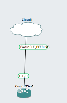
All fabric services are exposed via the GNS3 Cloud Appliance. Engineers can start a new topology in the lab environment and utilize the cloud appliance to connect to L2 and L3 VPNs.
L3VPN
To connect to the L3VPN, engineers can connect a router to the cloud appliance and configure BGP between the in-topology router and the L3VPN bridge interface.
example_rtr_1(config)#int g0/0
example_rtr_1(config-if)#ip add 172.16.4.26 255.255.255.248
example_rtr_1(config-if)#no shut
example_rtr_1(config-if)#router bgp 65045
example_rtr_1(config-router)#neighbor 172.16.4.25 remote-as 65000
example_rtr_1(config-router)#end
example_rtr_1#
*Jan  3 19:39:17.437: %SYS-5-CONFIG_I: Configured from console by console
example_rtr_1#
*Jan  3 19:39:21.094: %BGP-5-ADJCHANGE: neighbor 172.16.4.25 Up
example_rtr_1#
Once BGP is established, the in-topology router will learn any routes advertised into that particular VRF and can advertise its own prefixes into the VPN.
example_rtr_2(config)#int loop0
example_rtr_2(config-if)#ip add
*Jan  3 19:41:11.375: %LINEPROTO-5-UPDOWN: Line protocol on Interface Loopback0, changed state to up
example_rtr_2(config-if)#ip add 10.2.2.2 255.255.255.255
example_rtr_2(config-if)#router bgp 65055
example_rtr_2(config-router)#network 10.2.2.2 mask 255.255.255.255
example_rtr_2(config-router)#end
example_rtr_2#
*Jan  3 19:42:18.161: %SYS-5-CONFIG_I: Configured from console by console
example_rtr_2#
Traffic between these two routers will be label-switched between both GNS3 servers participating in the EXAMPLEVRF.
example_rtr_1#sh ip route bgp
Codes: L - local, C - connected, S - static, R - RIP, M - mobile, B - BGP
D - EIGRP, EX - EIGRP external, O - OSPF, IA - OSPF inter area
N1 - OSPF NSSA external type 1, N2 - OSPF NSSA external type 2
E1 - OSPF external type 1, E2 - OSPF external type 2
i - IS-IS, su - IS-IS summary, L1 - IS-IS level-1, L2 - IS-IS level-2
ia - IS-IS inter area, * - candidate default, U - per-user static route
o - ODR, P - periodic downloaded static route, H - NHRP, l - LISP
a - application route
+ - replicated route, % - next hop override, p - overrides from PfR
Gateway of last resort is not set
10.0.0.0/32 is subnetted, 1 subnets
B        10.2.2.2 [20/0] via 172.16.4.25, 00:00:31
172.16.0.0/16 is variably subnetted, 3 subnets, 2 masks
B        172.16.5.24/29 [20/0] via 172.16.4.25, 00:03:25
example_rtr_1#ping 10.2.2.2
Type escape sequence to abort.
Sending 5, 100-byte ICMP Echos to 10.2.2.2, timeout is 2 seconds:
!!!!!
Success rate is 100 percent (5/5), round-trip min/avg/max = 10/16/30 ms
example_rtr_1#
EVPN
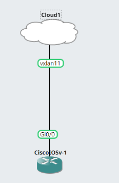
To utilize the EVPN, engineers can connect to the cloud appliance and treat the bridge interface as an entry point for a standard L2 segment.
example_rtr_1(config)#int g0/0
example_rtr_1(config-if)#ip addr 10
*Jan  3 19:51:21.684: %LINK-3-UPDOWN: Interface GigabitEthernet0/0, changed state to up
*Jan  3 19:51:22.686: %LINEPROTO-5-UPDOWN: Line protocol on Interface GigabitEthernet0/0, changed state to up.
example_rtr_1(config-if)#ip addr 10.0.0.1 255.255.255.0
example_rtr_1(config-if)#no shut
example_rtr_1(config-if)#end
example_rtr_1#sh arp
Protocol  Address          Age (min)  Hardware Addr   Type   Interface
Internet  10.0.0.1                -   0c01.768e.0000  ARPA   GigabitEthernet0/0
Internet  10.0.0.2                1   0c8d.79cd.0000  ARPA   GigabitEthernet0/0
example_rtr_1#
Traffic between these two routers will be encapsulated with VXLAN and routed to the remote server.
example_rtr_2(config)#int g0/0
example_rtr_2(config-if)#ip addr 10.0.0.2
*Jan  3 19:51:56.299: %LINK-3-UPDOWN: Interface GigabitEthernet0/0, changed state to up
*Jan  3 19:51:57.304: %LINEPROTO-5-UPDOWN: Line protocol on Interface GigabitEthernet0/0, changed state to up2
example_rtr_2(config-if)#ip addr 10.0.0.2 255.255.255.0
example_rtr_2(config-if)#no shut
example_rtr_2(config-if)#end
example_rtr_2#ping
*Jan  3 19:52:37.088: %SYS-5-CONFIG_I: Configured from console by console
example_rtr_2#ping 10.0.0.1
Type escape sequence to abort.
Sending 5, 100-byte ICMP Echos to 10.0.0.1, timeout is 2 seconds:
.!!!!
Even though these routers are on separate servers, they appear L2 adjacent, resolve remote MAC addresses via ARP, and run IGPs like OSPF.
Conclusion
We've covered a lot of ground in this article; we used Terraform to provision new instances, utilized remote and local exec provisioners to bootstrap our new hosts, and automated a networking config with Ansible. Using the implementation described here allows us to deliver a virtual lab environment for our engineers that scales to their needs and can support complex topologies and large amounts of utilization without significant engineering overhead. Terraform gives us the ability for anyone working on our platform to manage the lifecycle of new and existing instances with a simple YAML entry point. Ansible provides a means to address relatively complex networking and host OS configuration through structured data and idempotent tasks. All these tools coalesce to provide a way for us to move faster, deploy with more confidence, and remove vast amounts of human error.